 Loading... Please wait...
-
Call us on (559) 432-8873
- My Account
- Items / $0.00
All prices are in All prices are in USD
Categories
ARRL Product Review of the M2 6-Meter HO Loop Antennas
Posted by Bob Allison, WB1GCM on 14th Feb 2018
Reviewed by Bob Allison, WB1GCM
Assistant Laboratory Manager

The time had come to replace my three-element Yagi antenna for 6 meters. It was a homebrew affair, built during the remarkable solar peak of the late 1950s. The Alliance U-100 rotator that turned it was nearly asold and erratic. My wife, Kathy, KA1RWY, had bought the Yagi back in the 1980s for $20. The used rotator had been another $20, and the feed line was another $20. This $60 antenna system was only supposed to be a temporary arrangement, but as often happens, it ended up lasting for 28 years.
A new antenna was in order if we wanted to continue to enjoy 6 meters, which has many different propagation opportunities. After researching some new, good-quality directional antennas and rotators, I considered installing a loop antenna. The loop, mounted horizontally, does not require a rotator and provides an omnidirectional pattern. A loop is also lightweight and has a smaller wind profile than a Yagi and rotator, and is therefore easier to support.
According to some antenna experts, using two loops, stacked, might give e close to the same gain as what my old Yagi offered — about 6 dBd (6 dB better than a dipole) — but on all points of the compass. Working stations
without turning a beam during the VHF contests and roundtable nets that I enjoy sounded like it would work out pretty good, so I figured it was worth a try, and we ordered two 6-meter HO Loops and a stacking harness from M2 Antenna Systems.
The HO Loop is sturdy enough to go mobile, too. M2 offers a large magnetic mount for the enthusiast who never wants to miss a band opening. I didn’t try the mag mount, as I was mainly interested in a new antenna for my home station.
Arrival in the Lab
When the loops and power divider arrived, Pete Turbide, W1PT, found everything present (see Figure 3). Each loop is made out of two lengths of 3⁄8-inch OD aluminum tubing and is approximately 30 by 29.5 inches, weighs only 2 pounds, and has a surface area of 0.1 square feet.
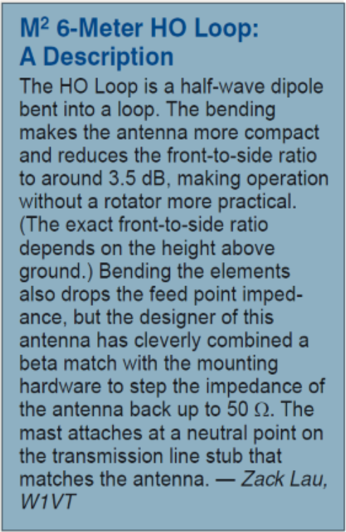
On the feed point side, the loop halves come together at a feed block with an SO-239 connector for the feed line. The feed block is part of an impedance-matching assembly with a shorting bar for tuning. (See the accompanying sidebar, “M2 6-
Meter HO Loop: A Description.”) In the center of the opposite side of the loop, the two halves are fastened to a UHMW (ultra-high molecular weight polyethylene) tube, which forms a capacitor. A 3⁄8-inch aluminum tube attaches to the UHMW tube and angles down to a mast clamp to support the loop. Two compression-type clamps are used to attach the loop to a mast or tower leg, and stainless steel hardware keeps corrosion at bay.
The power divider assembly is made of two lengths of unspecified RG-8 size coax, 43" and 143" inches long, with PL-259 connectors, plus a T-connector where the feed line to the station attaches.
Assembly Using the well-illustrated, step-by-step instructions (available for download from the M2 website), Pete had no difficulty assembling the loops and getting each one to match a 50 Ω transmitter output and transmission line. Most of my operating is from 50.090 to 50.400 MHz, so Pete adjusted the position of the feed block for a minimum SWR (1.1:1) at 50.2 MHz. If two loops are used, the feed assembly block must be reversed on the second loop to make that loop 180° out of phase with the other one. With the antennas built and tested, it was time to put them up at my house with help from Pete and Mike Gruber, W1MG. The ARRL September VHF Contest was coming up — a perfect opportunity to see how well the new system would work.


Figure 3 — The parts for one M2 6-meter HO Loop prior to assembly. Figure 4 — Mike Gruber, W1MG, and Pete Turbide, W1PT,
put the finishing touches on the M2 6-meter HO Loop antennas.
I had to purchase a new 30-foot mast, with the intention of using the recommended loop spacing of 12 feet (top antenna at 30 feet, bottom one at 18 feet). All of my existing masts were “TV grade” 1-inch-diameter masts, but HO Loop mast clamps require a 11⁄4- to 2-inch diameter mast or tower leg. While good-quality 10-foot, 11⁄4-inch-diameter mast sections are reasonably priced, shipping charges to get three of them to my house would add $100 to the cost. In an attempt to be frugal, I purchased three 10-foot sections of 11⁄4-inch, galvanized metal electrical conduit and two couplers for $45 at a local home improvement store. Unfortunately, the mast bent a bit at each coupling point, and we were very lucky a coupler didn’t break when raising the antenna and mast. Guying the mast stabilized it, but we decided it was a bad idea. For a proper installation, I ordered three 10-foot sections of Rohn 11⁄4-inch mast from DX Engineering. Each section has a swaged end to fit into the next section for strength and is made of 16-gauge galvanized steel. This created a solid, 30-foot mast, suitable for supporting two loops, a power divider, and coax cables at a cost of $168, shipping included. Figure 4 shows Mike and Pete finishing the assembly with the new mast.
On the Air
The installed HO Loops measured close to 1:1 SWR from 50 to 50.2 MHz (CW, beacons, and SSB) and 1.4:1 on 50.4 MHz (AM). That first evening, 6 meters was open to the south eastern US, with good signals for about 15 minutes. The
n the band closed abruptly (as often happens during sporadic-E openings). Over the next 2 weeks, I made several SSB contacts with stations around the northeast.
On 50.4 MHz AM, I met up with an old friend — Mike, WA1MTZ — some 34 miles to the northwest, and he had time to carefully listen to my signal, generated by my 1959-era Gonset G-50 running at 20 W. I left the support mast loose enough so I could rotate it, and during our contact, I tried various orientations. We noticed that signal strength varied by 1 to 2 S-units as I rotated the antenna. Signals were strongest with the loops oriented so that the feed point and the insulator of the antenna were in line toward his direction. There could be a couple of reasons why this is so. As noted in the sidebar, “M2 6-Meter HO Loop: A Description,” the exact front-to-side ratio depends on the height above ground, and my lower loop is only 18 feet above ground. It’s also possible that proximity to the roof of our house and the metal chimney affects the radiation pattern.
I always enjoy the ARRL VHF contests. Besides giving me an opportunity to speak to friends, the contests are excellent occasions to test equipment and antenna systems and try to beat my own last contest score. This time around, I ran 150 W into the HO Loops, which put me in the low power category for the event. Note that a pair of HO Loops is rated to handle 1.5 kW PEP (800 W for a single loop).
Unfortunately, there was no ionospheric or tropospheric enhancement during the event. With terrestrial propagation only, I was able to hear quite well and contacted 60 stations in 13 grid squares. Based on previous experiences, I’d say the results with the loops were comparable to my old three-element Yagi in terms of distance and signal strength.
Advantages and Disadvantages
A single loop or stacked loop system is a good option for use on 6 meters. The advantage is being able to hear equally well in all directions. The HO Loops antenna system makes a good listening antenna for the serious 6-meter operator who doesn’t want to miss a band opening because the beam is pointed in the wrong direction. Overall, the biggest advantage of using the M2 HO Loop system is that no rotator is required. Usually, my rotator gets a workout during a contest, and sometimes the station I’m after is gone by the time the antenna is pointed in the right direction. With the growing popularity of FT8 and other weak-signal digital modes, long-distance communication on 6 meters is possible more often than ever before. An omnidirectional antenna, such as the HO Loop, would be ideal for this mode, especially when you have no idea where signals might be coming from.
A disadvantage of omnidirectional loop systems is man made noise, which cannot be minimized by rotating the antenna away from the noise source. I am fortunate to have a reasonably low noise floor on 6 meters.
The two HO Loops and power divider reviewed here cost $505, not including the mast. That’s about the price of a good rotator and one of M2’s three element Yagis for 6 meters. The most expensive component of the stacked HO Loop antenna system is the power divider, at $189. If you’re handy, you might be able to build your own power divider.
Overall, I give M2 good marks on quality. It looks as though the loops will last at least 28 years, too. Manufacturer:
M2 Antenna Systems, 4402 N. Selland Ave., Fresno, CA 93722; www.m2inc.com. Price:6-Meter HO Loop, $158 each; Two-Port Power Divider Kit, $189.
**Published with permission of the ARRL**