 Loading... Please wait...
-
Call us on (559) 432-8873
- My Account
- Items / $0.00
All prices are in All prices are in USD
Categories
K6MYC on Antenna Testing
Posted by Mike Staal, K6MYC on 6th Jun 2017
Some TIPS on measuring VSWR and troubleshooting M2 Antennas and other commercially available HF antennas. In most cases these concepts are handy for VHF and UHF antennas as well.
1.If you are testing an antenna for the first time after assembling it from scratch or have refurbished a used antenna, it never hurts to use your Ohm meter and test for good continuity across each joint.
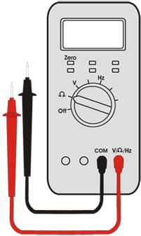
2.Set your Ohm meter on the lowest resistance range like 0 to 200 Ohms. Short the leads together and note the reading. It may not be 0.00 but it should be below one Ohm. Note this reading and be sure it is repeatable over 4 or 5 tries at shorting the leads together. Some meters drift slightly during your measurement time, so check your “shorted leads” reading every so often. If your readings are inconsistent or vary wildly you may have a poor connection at the meter itself or you may be picking up nearby AM broadcast RF. Correct the lead connection problem before continuing. To eliminate RF pickup, try some ferrite beads or snap on ferrite slugs on your leads as close as possible to the meter itself. For a quick test to see if RF is an issue, short the leads and fold them up in some aluminum foil. If the wild fluctuations stop, it means you should deal with the RF before you can continue
3.Now you can proceed checking the “continuity” across each joint. If the reading is over 0.10 Ohm more than your shorted lead reference reading, be suspicious. Make sure your lead tips are touching clean metal. It may sound silly, but most antenna problems can be found with JUST your Ohm meter. Be sure to take the visible reading instead of listening for the meter beep. Some meters beep even with several Ohms of resistance. Any resistive joint in an antenna can spell disaster or very poor or lousy performance.
4.Next, if all the joints are solid, you can try a simple RF listening test. Even if you have the antenna just a few feet above ground on wooden or plastic saw horses, it should sound quite lively with increased noise and signals when the feedline is attached to a receiver or transceiver. You can’t run F/B measurements, but you can listen a bit and if possible compare it to other antennas you may have. You can attempt to check the VSWR with a bridge, wattmeter or analyzer but don’t expect perfection. If possible, sweep across the frequency range plus some on either side of where the antenna is supposed to work. You should see that some peaks and nulls or more pronounced with better VSWR readings “in band” than way outside the band. Of course, it is important to know you have a GOOD piece of 50 Ohm coax for this test setup.
5.If you like what you have seen so far, it may be time to raise your HF antenna to 10 to 15 feet (4 to 7 ft. for VHF or UHF) over ground and repeat the VSWR check. Perhaps the antenna can be side mounted on your fixed tower or on top of your lowered crank up. At 20 to 25 feet over ground, on 20M and higher, you should start to see the VSWR curve take the correct shape. You should see much higher VSWR outside the band than in. Again, a receive test is always helpful and even cranked down at 21 to 25 feet, a F/B check can tell you if the antenna is looking promising.
6.If rotation is possible, you can also watch the VSWR change a bit as the antenna is pointed at or away from large nearby objects. If the VSWR is very good or acceptable at some in band frequency, this is a good sign even though the match may not be exactly where you want it. In a three element beam for instance, the reflector influences the lower end of the band and the director can pull the match to the high end. It may be helpful to think of the two parasitic elements in a tug of war with the driven element being the middle line in the battle. If you could somehow short out the director for a moment you would probably see the VSWR curve slide down a bit. Same thing if the reflector is momentarily shorted out, the VSWR curve should slide up a bit. If one or the other parasitic elements are not working properly or on the wrong frequency, this may cause the VSWR to be off a bit in frequency. This is not always the case, because the driven element could be off one way or the other and have a similar effect. It helps to know what affects what to analyze where to look for a potential problem.
7.The height over ground can also have some affect on the VSWR and where if is in the band. Generally, as you increase the height over ground, the antenna’s match and performance will move slightly higher in frequency. In most cases the match or VSWR was probably optimized by the manufacturer at a good working height of at least ½ wavelength of more. So, if your tests and measurements have been good up to this point, the next step may be to raise the antenna to it’s final working height and hopefully take some final measurements. This is much easier if the antenna is mounted on a crank up tower. If you are not happy and confident of your readings at 20-25 feet, don’t put the antenna all the way to the top of your fixed tower until you have made some more tests and measurements. Perhaps just raising it another 10 feet will give you numbers that look good. If nothing is jiving, it is probably best to get the antenna back on the ground and go over your measurements and assembly manual another time. It can be very helpful to have another person look over your shoulder to double check your efforts.