 Loading... Please wait...
-
Call us on (559) 432-8873
- My Account
- Items / $0.00
All prices are in All prices are in USD
Categories
Blog - driven element
M2 Driven Element Schematic & Trouble Shooting
Posted by M2 Support on 28th Oct 2015
Ever wondered how to check your Driven Element!
Check out the steps below to find out how!
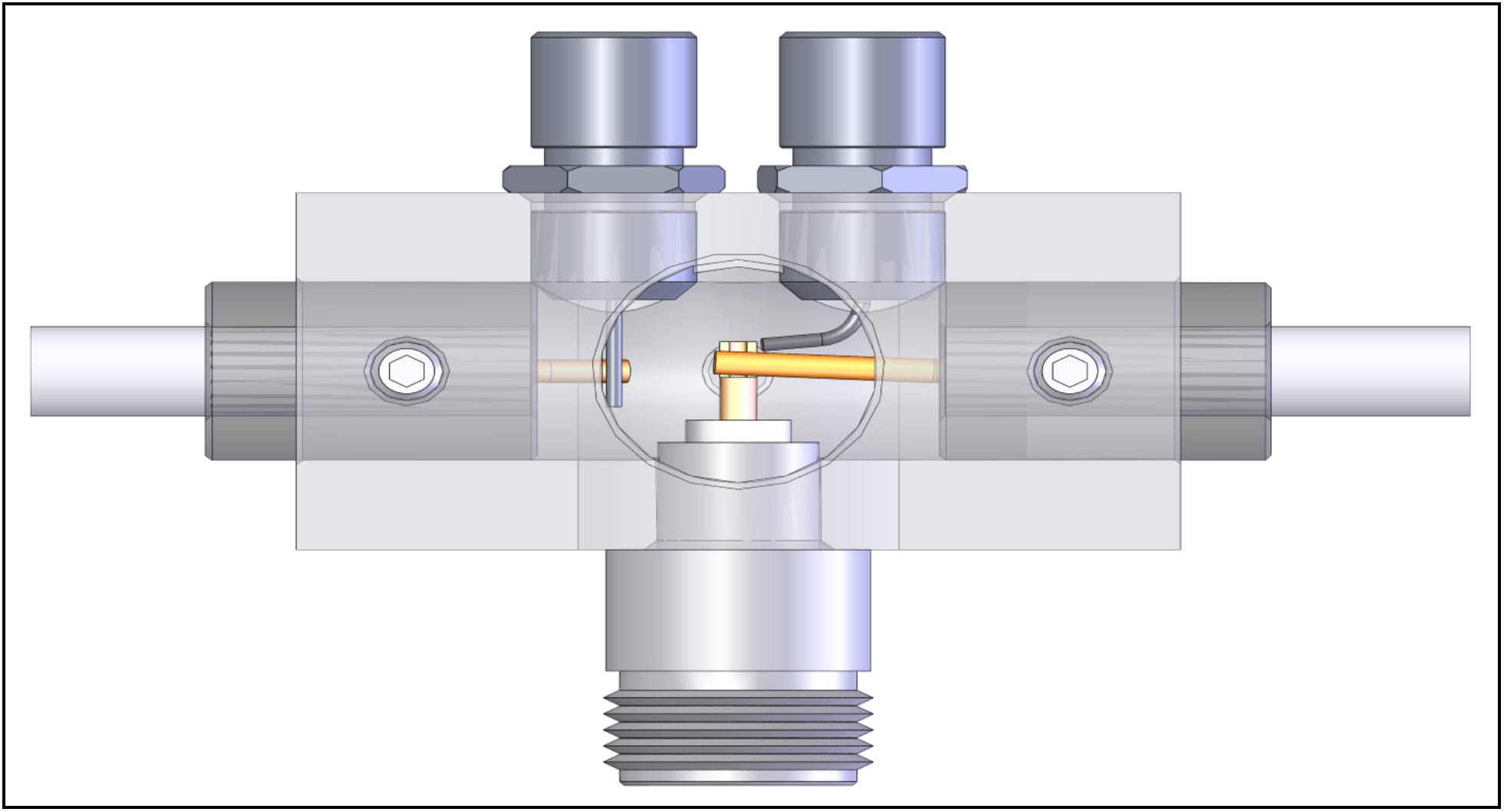
To check internal driven element block connections, remove balun, shorting bars, and feed coax/ phasing line.
Test Steps:
1.Continuity: between block & all connector Bodies.
2.Continuity: between N-connector center pin to one of the F-connector center pins and to the T-match rod on the same side.
3.Continuity: between the opposite F-connector center pin to the T-match rod on the same side.
4.No Continuity: between the two F-connector center pins.
5.No Continuity: between all center conductors & block / connector bodies.
6.Test balun cable connectors. There should be continuity from shield to shield, center wire to center wire and no continuity from the center wire to shield.
Continuity Defined:
- No Continuity= This means that the resistance shown on your meter when testing is over 1 meg ohms.
- Continuity = This means you should have 0.0 (0.1 ohm tolerance) or the same reading you get when shorting your meter leads.